
LED display and keypad driver
TM1637
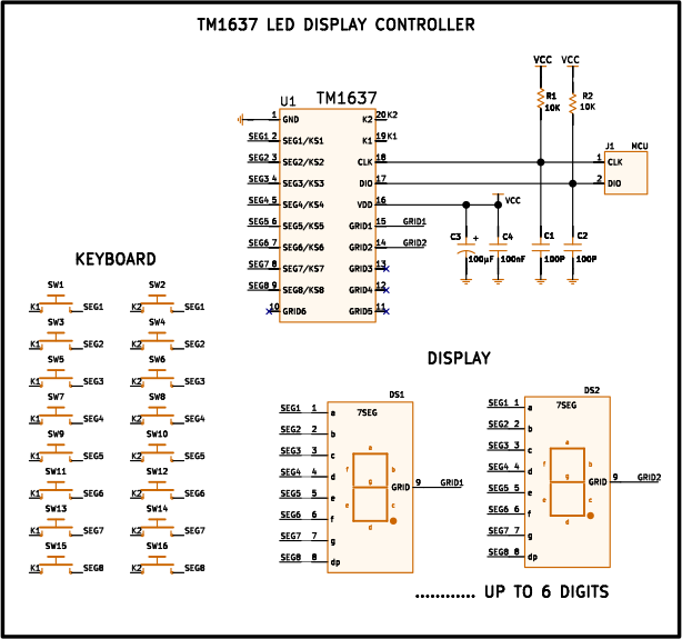
Pinout
| Pin | Function |
|---|---|
| GND | Logic ground (pin 1). |
| SEG1/KS1 | Segment 1 output, NMOS open-drain. Also a keypad scan input. |
| SEG2/KS2 | Segment 2 output, NMOS open-drain. Also a keypad scan input. |
| SEG3/KS3 | Segment 3 output, NMOS open-drain. Also a keypad scan input. |
| SEG4/KS4 | Segment 4 output, NMOS open-drain. Also a keypad scan input. |
| SEG5/KS5 | Segment 5 output, NMOS open-drain. Also a keypad scan input. |
| SEG6/KS6 | Segment 6 output, NMOS open-drain. Also a keypad scan input. |
| SEG7/KS7 | Segment 7 output, NMOS open-drain. Also a keypad scan input. |
| SEG8/KS8 | Segment 8 output (typically the decimal point), NMOS open-drain. Also a keypad scan input. |
| GRID6 | Digit-select output 6, PMOS open-drain. |
| GRID5 | Digit-select output 5, PMOS open-drain. |
| GRID4 | Digit-select output 4, PMOS open-drain. |
| GRID3 | Digit-select output 3, PMOS open-drain. |
| GRID2 | Digit-select output 2, PMOS open-drain. |
| GRID1 | Digit-select output 1, PMOS open-drain. |
| VDD | Logic supply, typically 5 V (3.6–5.5 V range). |
| DIO | Serial data input/output of the two-wire bus. |
| CLK | Clock input of the two-wire bus. |
| K1 | Return line 1 of the keypad matrix (8x2 keys). |
| K2 | Return line 2 of the keypad matrix (8x2 keys). |
TM1637
The TM1637 is an integrated circuit from Titan Micro Electronics dedicated to driving 7-segment LED displays and reading a keypad matrix, sharing most of its pins for both functions. It supports up to 6 digits × 8 segments and a matrix of up to 16 keys (8×2). It packs into a single chip what would normally require a dedicated microcontroller: data registers, the high-current drivers for the display, and the key-reading circuitry. It talks to the host microcontroller over a two-wire serial bus (CLK and DIO), cutting to just four the number of pins needed to drive a full display with a keypad.
The displays must be common anode: the GRID outputs (PMOS) source current to the shared anode of each digit, while the SEG outputs (NMOS) sink each individual segment to ground.
Although the manufacturer targets it at appliances (induction cooktops, microwaves, small appliances with a display), it is one of the most widely used chips in hobby electronics for 4-digit 7-segment clock and counter modules, thanks to how simple it is to wire up and the wide availability of libraries for almost any platform.
DIP20 / SOP20 package.
Pin diagram
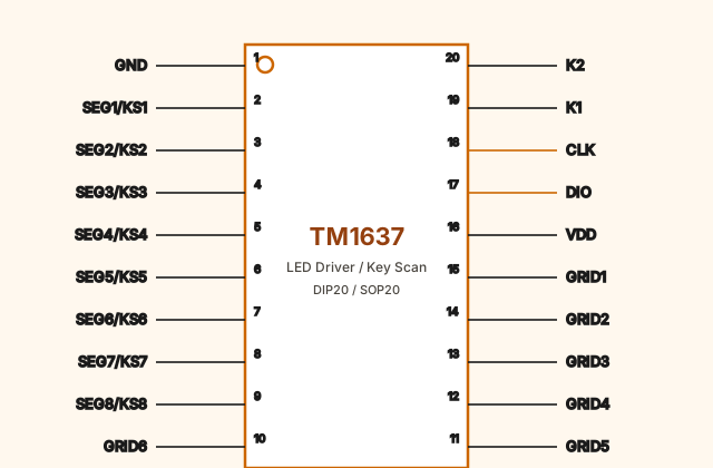
The eight SEG1–SEG8 pins do double duty: they drive the display segments (open-drain to ground) and, during the intervals when the display is blanked, act as keypad scan inputs. The six GRID1–GRID6 pins select which digit is active (open-drain toward VDD). K1 and K2 are the two return lines of the keypad matrix.
How it works
Display multiplexing. The TM1637 doesn’t keep all 6 digits lit at once: it turns
on one GRID (digit) at a time, with the matching segment pattern on the SEG
outputs, and cycles through the six digits fast enough that the human eye sees all
six lit continuously (persistence of vision). Brightness is set by an internal
8-level PWM circuit: the wider the on-pulse of each digit within its turn, the
brighter it appears.
Keypad scanning. During the gaps when the display is blanked, the chip reuses the
SEG lines as inputs and checks whether any key wired between a SEGn line and
K1/K2 is pressed, forming a matrix of up to 16 keys (8x2). The chip itself
filters bounce and the noise typical of appliances with motors (induction cooktops,
microwaves) through an edge-triggered recognition circuit.
All of this — multiplexing, brightness, keypad reading — is handled autonomously by the TM1637 once configured: the microcontroller only needs to write the segment patterns to display and, optionally, read the keypad state.
Communication protocol
The TM1637 uses a two-wire serial bus (CLK, DIO) that looks like I²C in the shape of its transactions — a START condition, bytes with an ACK bit, a STOP condition — but it is not I²C: there’s no 7-bit address for multiple devices on the same bus (only one TM1637 can sit on a bus) and the meaning of each byte is defined by the chip’s own command set, not a standard protocol.
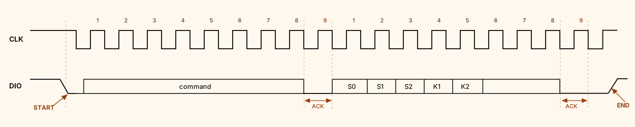
The diagram corresponds to the keypad read example: after the command byte
(the read-keys instruction), the TM1637 itself takes over DIO and returns a second
byte made up of the fields S0–S2 (which SEGn line detected the pressed key) and
K1–K2 (which return line, K1 or K2, was active). Each of the two bytes in the
transaction ends with one extra clock pulse (number 9) during which the chip
briefly forces DIO low to confirm receipt (ACK); that’s the small arrow marked
under each pulse 9 in the diagram.
Basic signaling rules:
- DIO bits must be stable on every rising edge of CLK, which is the instant they get sampled; they can only change while CLK is low.
- START: DIO falls from high to low while CLK is high.
- STOP: DIO rises from low to high while CLK is high.
- Each byte is sent least significant bit first. After the 8 bits, the chip generates a ninth clock pulse during which it forces DIO low as an acknowledgement (ACK) that it received the byte correctly.
- Clock frequency can go up to 500 kHz for writes, but must be kept under 250 kHz when reading keypad data.
What bytes are sent. The two most significant bits of the first byte in each transaction indicate the command type:
| High bits | Command | Purpose |
|---|---|---|
01 | Data command | Sets whether the display is written or the keypad is read, and whether the address auto-increments or stays fixed |
11 | Address command | Selects which digit (00H–05H) the next data byte is written to |
10 | Display control command | Turns the display on/off and sets the brightness (8 levels) |
Typical sequence to write the display: START → data command (write mode, auto-increment address) → ACK → address command (00H) → ACK → up to 6 bytes with the segment pattern for each digit, each followed by its ACK → STOP → START → display control command (on, brightness) → ACK → STOP.
To read the keypad: START → data command with the read bit set → ACK from the chip → the TM1637 takes over DIO and sends 1 byte with the key state → the master generates its own ACK (or not) → STOP.
Other applications
Beyond the appliance examples from the manufacturer itself (induction panels, microwaves, small appliances), the TM1637 is mainly used in:
- 4-digit clocks and timers. The most popular DIY module, with 4 seven-segment displays and a center colon for the hour separator.
- Counters and scoreboards. Numeric displays with increment/decrement buttons taking advantage of the built-in keypad scanning.
- Measurement readouts. Showing temperature, voltage, RPM, or other numeric values read by a microcontroller, using no more than two I/O pins.
References and further reading
- PDFTM1637 datasheet
This is the main source this article was created from.
- WEB