
Square wave oscillator
LM324
Pinout
| Pin | Function |
|---|---|
| V+ | Positive supply for the operational amplifier (3 to 32 V single supply). |
| GND | Supply ground (pin 11 on the 14-pin package). |
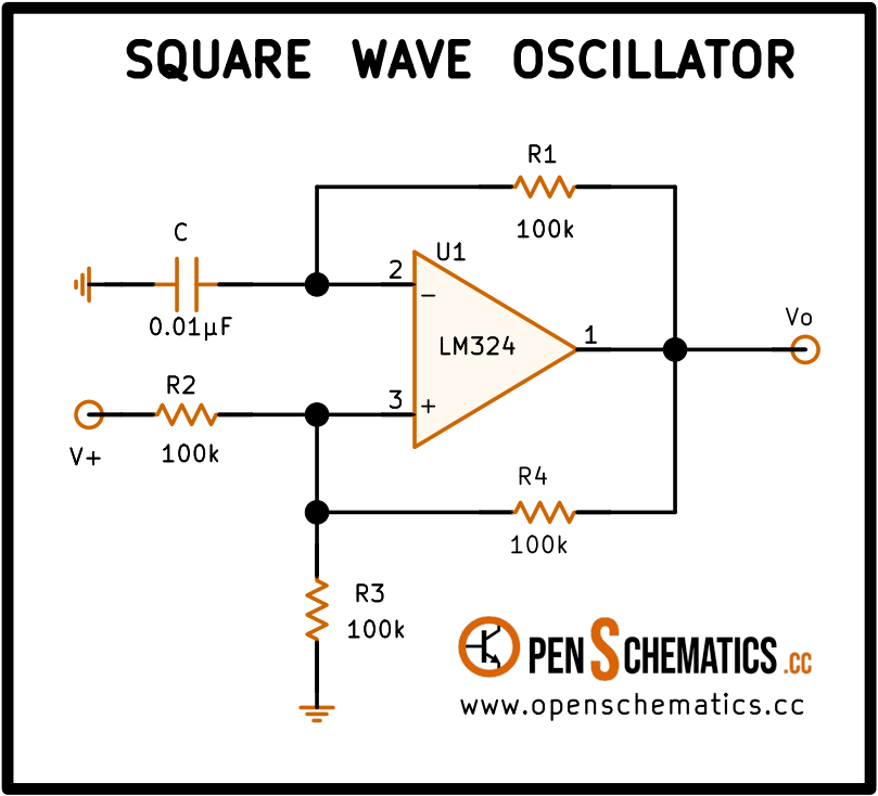
| IN+ (pin 3) | Non-inverting input of amplifier 1. Receives the reference voltage set by the R2-R3 divider. |
| IN− (pin 2) | Inverting input of amplifier 1. Receives the capacitor voltage through R1. |
| OUT (pin 1) | Output of amplifier 1. Switches between V+ and GND to produce the square wave (Vo). |
LM324
The LM324 is a quad general-purpose operational amplifier made by Texas Instruments. It packs four independent amplifiers into a single 14-pin package and runs from a single supply of 3 to 32 V or a split supply of ±1.5 to ±16 V. Its input range extends down to the negative rail, which simplifies single-supply designs. Power consumption is low and the bandwidth is roughly 1 MHz, more than enough for low-frequency applications like this oscillator.
This circuit uses only one of the four amplifiers (U1, pins 1-2-3). The remaining three are available for other tasks or should have their inputs tied to ground to prevent spurious oscillation.
How the circuit works
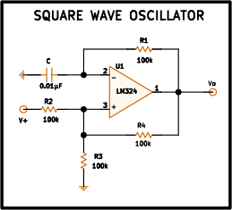
The circuit is a classic astable oscillator that produces a square wave at the output Vo by exploiting the op-amp’s positive feedback. It needs just five components: one amplifier (U1), four resistors (R1–R4) and one capacitor (C).
Positive feedback (R4). Resistors R2 and R3, both 100 kΩ, form a voltage divider between V+ and ground, while R4 (100 kΩ) connects the output Vo to the non-inverting input (+). The three equal resistors set the (+) input at (V+ + Vo)/3. When the output is high (≈ V+), the (+) input sits at V+×2/3; when the output is low (≈ 0 V), the (+) input drops to V+×1/3. This network sets the oscillator’s switching thresholds.
Timing (R1-C). Capacitor C (0.01 µF) charges and discharges through R1 (100 kΩ), which is connected between the output and the inverting input (−). The voltage at (−) follows an exponential rising toward V+ or falling toward 0 V depending on the output state.
Oscillation cycle. Assume the output starts high:
- C charges through R1 toward V+. The voltage at (−) rises.
- When the voltage at (−) exceeds the (+) threshold (V+×2/3), the amplifier switches: the output goes low.
- Now C discharges through R1 toward 0 V. The voltage at (−) falls.
- When the voltage at (−) drops below the new (+) threshold (V+×1/3), the amplifier switches back to high.
The process repeats indefinitely, producing a square wave at Vo.
Application design
Oscillation frequency
The frequency depends on R1, C and the thresholds set by R2, R3 and R4. With all three resistors equal, the thresholds sit at V+/3 and 2V+/3, and the frequency is approximately:
With the schematic values (, ):
Adjusting the frequency
To change the frequency, modify R1 or C:
Doubling R1 or C halves the frequency. Replacing C with 0.1 µF lowers it to roughly 72 Hz; using 1 nF raises it to about 7.2 kHz. The practical range is limited by the LM324’s bandwidth (~1 MHz) and slew rate (~0.5 V/µs), which rounds off the edges at higher frequencies.
Duty cycle
With the symmetric thresholds at V+/3 and 2V+/3, both half-cycles have the same duration and the duty cycle is ideally 50 %. In practice the LM324’s output does not reach exactly V+ or 0 V, which introduces a slight asymmetry. If a precise square wave is needed, consider a rail-to-rail output op-amp or a dedicated comparator.
Power consumption
The LM324 draws a typical quiescent current of about 375 µA per amplifier. The oscillator circuit adds the current through the R2-R3 divider and R4, which at 100 kΩ and a 5 V supply is on the order of 50 µA per branch. Total circuit consumption stays below 1 mA at 5 V, making it suitable for battery-powered applications.
Other applications
Beyond the square wave oscillator described here, the LM324 is used in a wide variety of analog circuits:
- Voltage comparator. The same topology without the timing capacitor: the amplifier compares two voltages and outputs high or low.
- Instrumentation amplifier. Combining two or three of the four internal amplifiers to measure small differential signals with high input impedance.
- Active filters. Low-pass, high-pass or band-pass for signal conditioning in sensors, audio or control loops.
- Triangle wave generator. Adding an integrator stage after the square wave oscillator produces a triangular ramp.
- Simple linear regulator. As the error amplifier in low-power regulated supplies.
References and further reading
- PDFLM324 datasheet
This is the main source this article was created from.
- WEB