
USB keyboard and mouse emulator via serial port
CH9329
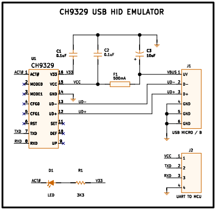
Pinout
| Pin | Function |
|---|---|
| ACT# | USB configuration completed status output, active low. |
| MODE0 | Operating mode configuration pin 0, with internal pull-up resistor. Works together with MODE1. |
| MODE1 | Operating mode configuration pin 1, with internal pull-up resistor. Works together with MODE0. |
| CFG0 | Serial communication mode configuration pin 0, with internal pull-up resistor. Works together with CFG1. |
| CFG1 | Serial communication mode configuration pin 1, with internal pull-up resistor. Works together with CFG0. |
| RST | External reset input, active high, with internal pull-down resistor. |
| TXD | Serial data output (UART TX). |
| RXD | Serial data input (UART RX), with internal pull-up resistor. |
| UP | USB data packet upload success indication. Level toggles with each successfully sent packet. |
| DEF | Factory settings restore pin. Hold low for more than 3 s to reset all parameters to factory defaults, with internal pull-up resistor. |
| SET | Parameter configuration pin, active low, with internal pull-up resistor. Forces protocol transmission mode while held low. |
| UD+ | USB D+ signal. Connect directly to USB connector. |
| UD- | USB D− signal. Connect directly to USB connector. |
| GND | Circuit ground. |
| VCC | Power supply input (3.7–5.5 V). Requires a 0.1 µF decoupling capacitor. |
| V33 | Internal USB regulator output (3.3 V). Connect to VCC when running at 3.3 V; connect a 0.1 µF capacitor when VCC is 5 V. |
CH9329
The CH9329 is an integrated circuit from Nanjing Qinheng Microelectronics Co., Ltd. (WCH) that converts data received over UART into USB HID packets, allowing any device with a serial port to emulate a keyboard, a mouse, or a custom HID device to a computer. The PC recognizes it as a standard USB peripheral and requires no additional drivers: Windows, Linux, Android, and macOS come with the necessary drivers preinstalled.
The chip integrates all the required USB circuitry: an internal crystal oscillator, a PLL with a 24 MHz USB clock, D+/D− signal matching resistors, a 1.5 kΩ pull-up for device identification, and an internal 3.3 V regulator for the USB transceiver. The external circuit comes down to two decoupling capacitors and the USB connector.
Serial communication uses a standard format (1 start bit, 8 data bits, 1 stop bit) with a default baud rate of 9600 bps, configurable up to 115200 bps (the latter only when powered at 5 V).
SOP-16 package.
How it works
Operating modes. Two pins (MODE0 and MODE1) select one of four operating modes that determine how the chip identifies itself to the computer:
| Mode | MODE1 | MODE0 | Function |
|---|---|---|---|
| 0 | 1 | 1 | Standard keyboard + mouse + custom HID (default) |
| 1 | 1 | 0 | Standard keyboard only (ordinary keys, no multimedia) |
| 2 | 0 | 1 | Standard keyboard + mouse (recommended on Linux/Android/macOS) |
| 3 | 0 | 0 | Custom HID only (transparent serial ↔ HID transmission) |
If MODE0 and MODE1 are left floating, the chip defaults to mode 0, the most comprehensive: keyboard with ordinary and multimedia keys, relative and absolute mouse, and a custom HID channel.
Serial communication modes. Two more pins (CFG0 and CFG1) select how the serial frame received by the CH9329 must be formatted:
| Serial mode | CFG1 | CFG0 | Description |
|---|---|---|---|
| 0 | 1 | 1 | Structured protocol (default). Each frame follows a format defined by the manufacturer. Required to use keyboard and mouse simultaneously. |
| 1 | 1 | 0 | ASCII. Visible ASCII characters or section-position code Chinese characters are sent directly. Covers visible character keys only. |
| 2 | 0 | 1 | Transparent transmission. Raw hexadecimal data with no framing; every 8 bytes form a USB packet. Suited for operating mode 3. |
If CFG0 and CFG1 are left floating, mode 0 (protocol) is selected — the most versatile.
Control pins. The ACT# pin goes low to indicate that the USB connection with the computer has been established successfully. The UP pin toggles its level each time a data packet is uploaded successfully. The SET pin, when pulled low, makes the chip temporarily enter protocol mode so its parameters can be reconfigured from the serial device. The DEF pin, held low for more than 3 s, restores all parameters to factory defaults.
Advanced configuration. Through the PC software provided by WCH, users can customize the operating mode, serial communication mode, baud rate, communication address (allowing multiple CH9329 chips on the same serial bus), timeout periods, the Enter character, filter strings, and the USB descriptors (VID, PID, manufacturer, product and serial number strings). Parameters are stored permanently inside the chip and survive power cycles.
Power supply. The supply voltage range is 3.7 to 5.5 V. When running at 5 V, the V33 pin connects to a 0.1 µF decoupling capacitor (the internal regulator generates 3.3 V for the USB transceiver). When running at 3.3 V, V33 is tied directly to VCC. Typical static current consumption is 11 mA.
Other applications
Beyond keyboard and mouse emulation, the CH9329 is used in:
- Automation and remote control. Sending keystrokes or mouse movements to a PC from a microcontroller, PLC, or embedded system without needing special software on the computer side.
- KVM and switches. Integration into IP- or serial-based KVM solutions where the remote device needs to inject keyboard and mouse events into the controlled computer.
- Testing and debugging. Emulating human input for software testing, BIOS automation, or repetitive tasks on machines that only accept standard HID devices.
- Custom HID devices. In mode 3 (custom HID), the chip acts as a bidirectional serial ↔ USB bridge for generic data transmission without requiring a driver, useful in instrumentation and data acquisition devices.
References and further reading
- PDFCH9329 datasheet
This is the main source this article was created from.
- WEB