
Force/weight sensor
HX711
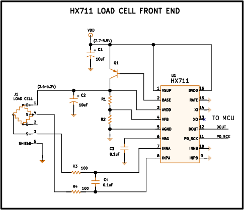
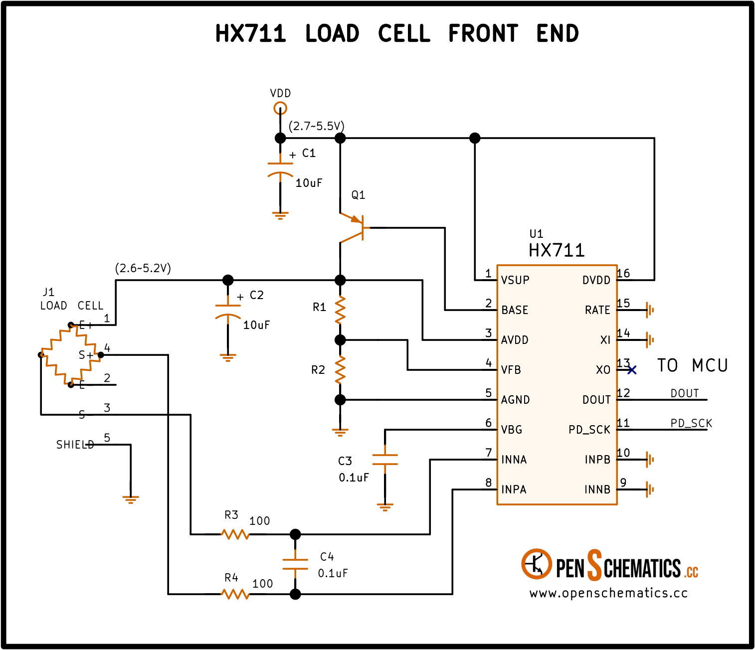
Pinout
| Pin | Function |
|---|---|
| VSUP | Internal regulator supply (2.7–5.5 V). |
| BASE | Regulator control output. Connects to the base of the external PNP transistor. NC when the regulator is not used. |
| AVDD | Analog supply (2.6–5.5 V). Powers the ADC and serves as the gain reference. |
| VFB | Regulator feedback input. Connect to AGND when the regulator is not used. |
| AGND | Analog ground. |
| VBG | Internal bandgap reference output (1.25 V typical). A 0.1 µF bypass capacitor is recommended. |
| INA− | Channel A differential negative input. |
| INA+ | Channel A differential positive input. |
| INB− | Channel B differential negative input. |
| INB+ | Channel B differential positive input. |
| PD_SCK | Serial clock input and power-down control. Holding high for more than 60 µs activates low-power mode. |
| DOUT | Serial data output. Goes low to indicate data ready. |
| XO | Crystal I/O. NC when using the internal oscillator. |
| XI | Crystal or external clock input. Connect to GND to use the internal oscillator. |
| RATE | Sample rate selection. Low = 10 SPS, high = 80 SPS. |
| DVDD | Digital supply (2.6–5.5 V). |
HX711
The HX711 is a 24-bit analog-to-digital converter (ADC) from Avia Semiconductor, designed specifically to interface load cells and bridge sensors directly with a microcontroller. It integrates a low-noise programmable gain instrumentation amplifier (PGA), a two-channel differential input multiplexer, an analog supply regulator, and an internal oscillator, so the external circuit comes down to a handful of passive components.
It requires no configuration registers or bus programming: all control is done through the number of clock pulses and pin levels. The conversion result is output through a two-wire serial interface (DOUT and PD_SCK).
SOP-16 package.
How it works
Input channels. The HX711 has two differential inputs. Channel A offers a selectable gain of 128 or 64, corresponding to a full-scale differential input range of ±20 mV or ±40 mV respectively (with AVDD = 5 V). This is the primary input for the load cell. Channel B has a fixed gain of 32 (±80 mV full-scale) and is typically used for auxiliary functions such as battery level monitoring.
Analog supply regulator. The chip includes a linear regulator that generates AVDD from VSUP, eliminating the need for a dedicated external regulator. It uses an external PNP transistor (e.g. S8550) whose base is driven from the BASE pin, and the output voltage is set by a resistor divider on the VFB pin according to V_AVDD = V_BG × (R1 + R2) / R1, where V_BG is the internal 1.25 V bandgap reference. If the regulator is not needed, connect VFB to AGND and leave BASE unconnected.
Clock and sample rate. The internal oscillator is activated by connecting XI to GND, with no external components. The sample rate is selected via the RATE pin: low gives 10 SPS (best signal-to-noise ratio, simultaneous 50 and 60 Hz rejection) and high gives 80 SPS (faster, useful for dynamic dosing). Alternatively, an 11.0592 MHz crystal can be connected across XI and XO, or an external clock can be AC-coupled through a 20 pF capacitor to the XI pin.
Serial interface. All communication with the microcontroller is done through two pins: PD_SCK (clock, input) and DOUT (data, output). When a new reading is ready, DOUT goes low. The microcontroller applies 25, 26, or 27 clock pulses on PD_SCK to read the 24 bits (MSB first) and select the channel and gain for the next conversion:
| PD_SCK pulses | Next channel | Gain |
|---|---|---|
| 25 | A | 128 |
| 26 | B | 32 |
| 27 | A | 64 |
Low-power mode. If PD_SCK is held high for more than 60 µs, the chip enters power-down mode (current draw below 1 µA). Bringing PD_SCK back low resets the chip and returns it to normal operation with channel A and gain 128 as the default.
Other applications
Although its most widespread use is in digital scales, the HX711 is also found in:
- Industrial process control. Force, torque, or pressure measurement with Wheatstone bridge sensors in production environments, taking advantage of the 24-bit ADC’s high resolution.
- Dosing and filling. Dynamic weighing systems for filling containers to a target weight, using the 80 SPS rate for fast response.
- Laboratory instrumentation. Strain measurement with strain gauges in materials or structural testing.
- Battery level monitoring. Channel B, with its fixed gain of 32, can measure proportionally larger voltages, useful for monitoring battery state in portable systems powered from the same VSUP.
References and further reading
- PDFHX711 datasheet
This is the main source this article was created from.
- WEB
- WEB