
Photodiode light sensor
LM324
Pinout
| Pin | Function |
|---|---|
| V+ | Positive supply for the operational amplifier (3 to 32 V single supply). |
| GND | Supply ground (pin 11 on the 14-pin package). |
| IN+ (pin 3) | Non-inverting input of amplifier 1. Tied to ground to set the 0 V reference. |
| IN− (pin 2) | Inverting input of amplifier 1. Receives the photodiode current (virtual ground). |
| OUT (pin 1) | Output of amplifier 1. Voltage proportional to the photodiode current (Vo). |
Photodiode amplifier with the LM324
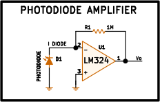
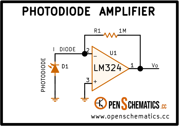
This circuit converts the reverse current of a photodiode into a voltage proportional to the intensity of light it receives. It is the most straightforward way to build an analogue light sensor with an operational amplifier: a single active device (one channel of the LM324), a feedback resistor R1, and the photodiode.
The topology is known as a transimpedance amplifier (TIA) because its gain is not a voltage ratio but a voltage-to-current ratio: volts per ampere, i.e. ohms. With R1 = 1 MΩ, every microampere of photocurrent produces 1 V at the output.
How it works
Photodiode D1 is connected with its cathode at the inverting input (−) and its anode to ground. The non-inverting input (+) is also tied to ground. Thanks to negative feedback through R1, the op-amp forces the inverting input to stay at virtual ground: the voltage at that node is held at essentially 0 V.
When light hits the photodiode it generates a reverse current (photocurrent) that flows from cathode to anode inside the device. Externally this means current leaves the inverting-input node toward ground. To maintain virtual ground the op-amp compensates by pushing exactly the same current through R1 from its output. The result is:
With R1 = 1 MΩ and a typical photodiode producing between 0.1 µA and a few µA under moderate illumination, the output sits in a range of tens of millivolts to several volts — comfortably within the input range of an analogue-to-digital converter.
The photodiode operates here in photovoltaic mode (virtually zero bias voltage), since both terminals sit at 0 V. This minimises dark current and noise at the cost of somewhat lower bandwidth compared to photoconductive mode (reverse-biased). For most low-frequency light sensors it is the preferred configuration.
Choosing R1
The feedback resistor R1 sets the sensitivity of the circuit:
| R1 | Sensitivity | Typical use |
|---|---|---|
| 100 kΩ | 0.1 V/µA | Bright light, high-current photodiodes |
| 1 MΩ | 1 V/µA | Medium illumination, general purpose |
| 10 MΩ | 10 V/µA | Low light, weak optical signals |
Increasing R1 raises sensitivity but also increases noise and reduces bandwidth. Above a few MΩ it is advisable to add a small capacitor in parallel with R1 (a few pF to tens of pF) to prevent oscillation caused by the parasitic capacitance of the photodiode.
LM324 limitations
The LM324 accepts input voltages down to ground (low-rail-to-rail input), which allows the non-inverting input to be tied directly to GND — something many op-amps cannot tolerate. However it has some constraints:
- Speed. Its bandwidth (1 MHz, slew rate 0.5 V/µs) limits the circuit to low-frequency optical signals: ambient light sensors, slow infrared barriers, static optical power measurement.
- Minimum output voltage. The LM324 output cannot go below about 20 mV above GND, introducing a small dark-condition offset.
- Input bias current. The typical 20–45 nA bias current of the LM324 produces an offset of 20–45 mV with R1 = 1 MΩ. For precision work a JFET- or CMOS-input amplifier is preferable.
For fast optical signals (fibre communication, laser pulses) dedicated TIA ICs with MHz-to-GHz bandwidths are used instead.
Applications
- Ambient light sensor. Measuring light intensity for automatic lighting control, solar inverters, or weather stations.
- Infrared barrier. An emitting infrared LED and a receiving photodiode form a beam-break barrier for part counters, presence detectors, and wheel encoders.
- Pulse oximetry. Finger-clip pulse oximeters use two LEDs (red and infrared) and a photodiode with a transimpedance amplifier to measure haemoglobin absorption and calculate blood oxygen saturation.
- Optical power measurement. In fibre optics and laboratory settings a calibrated photodiode with a TIA measures the power of a laser beam or LED source.
- Short-range optical communication. Infrared remote controls and low-speed optical links use this same topology as the receiver front-end.
References and further reading
- PDFLM324 datasheet
This is the main source this article was created from.
- WEB
- WEB