
10-LED bar voltmeter
LM3914
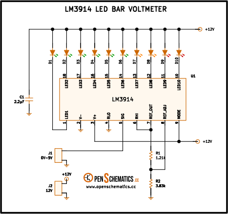
Pinout
| Pin | Function |
|---|---|
| Pin 1 (LED1) | First LED current output, low end of the scale. It is a programmable constant-current sink. |
| Pin 2 (V−) | Negative supply terminal. Tied to ground when the IC runs from a single supply. |
| Pin 3 (V+) | Positive supply. Accepts 3 V to 25 V from a single rail. |
| Pin 4 (RLO) | Low end of the internal divider chain, which sets the start of the measurement scale. |
| Pin 5 (SIG) | Signal input. A high-impedance buffer that does not load the source. |
| Pin 6 (RHI) | High end of the internal divider chain, which sets the full-scale value. |
| Pin 7 (REF OUT) | 1.25 V internal reference output, programmable with two external resistors. |
| Pin 8 (REF ADJ) | Reference adjust terminal. The resistor to ground sets the output voltage at REF OUT. |
| Pin 9 (MODE) | Display mode select. Tied to V+ turns the display into bar mode; open or at V− leaves it in dot mode. |
| Pin 10 (LED10) | Tenth and last LED current output, high end of the scale. |
| Pin 11 (LED9) | Ninth LED current output. |
| Pin 12 (LED8) | Eighth LED current output. |
| Pin 13 (LED7) | Seventh LED current output. |
| Pin 14 (LED6) | Sixth LED current output. |
| Pin 15 (LED5) | Fifth LED current output. |
| Pin 16 (LED4) | Fourth LED current output. |
| Pin 17 (LED3) | Third LED current output. |
| Pin 18 (LED2) | Second LED current output. |
LM3914
The LM3914 is a linear 10-LED display driver. It integrates a precision divider network tapped by ten comparators spaced evenly along it, a programmable 1.25 V voltage reference and a high-impedance signal buffer. Each output is a constant-current sink that sets the current through its LED on its own — no series limiting resistor needed.
A mode pin picks between dot (only the LED that matches the level) and bar (all LEDs lit up to the level) display, and the scale is programmed with two external resistors. The IC runs from a single supply between 3 V and 25 V, which lets it sit alongside most analog circuits.
How it works
The signal to measure enters at pin 5 (SIG) and reaches the internal buffer, which compares it in parallel against the ten taps of the internal divider chain. That chain spans from pin 6 (RHI, high end) to pin 4 (RLO, low end). In this circuit RLO is tied to ground and RHI is tied to pin 7 (REF OUT), so the full-scale voltage equals the programmed reference.
Pins 7 and 8 form the programmable reference. R1 (1.21 kΩ) between REF OUT and REF ADJ, together with R2 (3.83 kΩ) between REF ADJ and ground, set the voltage at REF OUT to about 5 V — the full-scale value for a 0 V to 5 V input range.
Pin 9 (MODE) picks the presentation: here it goes straight to V+, so the display works in bar mode: the higher the signal, the more LEDs on at the same time. C1 (2.2 µF) decouples the +12 V rail that feeds the LED anodes and absorbs the current step as they turn on. D1–D6 are green, D7–D8 yellow and D9–D10 red, reproducing the classic “green-yellow-red” visual code as the level climbs toward full scale.
Since each output is a built-in constant-current source, no series resistor is needed on any LED: the LM3914 itself sets the same current for all ten.
Application design
Full-scale voltage
With R1 and R2 between REF OUT, REF ADJ and ground, the internal 1.25 V reference is amplified as:
where is the typical REF ADJ pin current. With and :
Enough to cover a 0 V to 5 V input with a small margin above. Each LED lights roughly every 500 mV ().
LED current
The LED current is ten times the current flowing through the internal divider chain, which R1 pins down:
A comfortable value for standard 3 mm or 5 mm LEDs. To boost brightness, lower R1 (and recompute R2 to keep the full-scale value); to dim the display, raise it.
Supply and bar mode
In bar mode with all ten LEDs on, the IC draws about 100 mA from the +12 V rail, so the supply must handle that comfortably. The 2.2 µF C1 capacitor close to the IC is a must: it prevents oscillation and keeps the anode rail stable when the LEDs switch on together.
Other applications
The LM3914 fits any analog indication where a 10-step bargraph reads better than a dial or a numeric display:
- Analog panel voltmeter. The direct use of this schematic, with the scale programmed by R1/R2 to any range.
- Battery charge indicator. With a divider on the input the full scale is calibrated to the typical maximum (e.g. 14.4 V for lead-acid).
- Audio VU meter. Preceded by a rectifier and a low-pass filter it shows the level of an audio signal on a bargraph.
- Thermometer with the LM35 or similar. The 10 mV/°C output of the LM35 drives SIG directly and the scale covers the range of interest.
- Fluid level or position indicator. A potentiometer or distance sensor provides the input signal for a 10-step visual strip.
References and further reading
- PDFLM3914 datasheet
This is the main source this article was created from.
- WEB